 2023, Vol. 41
Institute of Oceanology, Chinese Academy of Sciences
Article Information
- YU Junhui, YAN Pin, WANG Yanlin, QIU Yan, TU Guanghong, CHEN Changliang
- Origin of a giant fuzzy reflection zone and its implication for natural gas exploration in the southwestern Qiongdongnan Basin of the South China Sea
- Journal of Oceanology and Limnology, 41(2): 710-728
- http://dx.doi.org/10.1007/s00343-022-1452-3
Article History
- Received Dec. 31, 2021
- accepted in principle Mar. 21, 2022
- accepted for publication Apr. 12, 2022


2 Southern Marine Science and Engineering Guangdong Laboratory (Guangzhou), Guangzhou 511458, China;
3 Key Laboratory of Marine Geology and Environment, Institute of Oceanology, Chinese Academy of Sciences, Qingdao 266071, China;
4 Key Laboratory of Marine Mineral Resources, Guangzhou Marine Geological Survey, China Geological Survey, Ministry of Natural Resources, Guangzhou 511458, China;
5 University of Chinese Academy of Sciences, Beijing 100049, China
Layered sedimentary sequences can be disturbed by fluid charging or magma intrusion to generate obscure, chaotic or blank reflections, i.e., fuzzy reflection zones (FRZs) on seismic profiles (Baraza and Ercilla, 1996; Karisiddaiah and Raju, 2002; Lei et al., 2011a; Chen et al., 2013; Lei and Ren, 2016; Zhao et al., 2016; Wan et al., 2019; Wu et al., 2020). Generally, fluid charged sediments often rich in oil/ gas feature lower seismic velocity than surrounding sequences (Wu et al., 2009; Man et al., 2018; Wang et al., 2020), whereas magma intrusion leads to velocity increase (Lei and Ren, 2016; Zhao et al., 2016). There are numerous cases of fluid-charged low-velocity FRZs, which have been proven to be important hydrocarbon migration pathways and reservoirs and contribute significantly to the formation of large oil/gas fields or gas hydrates, e.g., the liquid diapirs and associated large gas fields (DF1-1, LD22-1, etc.; Fig. 1) in the central depression of the Yinggehai Basin (YGHB) (Huang et al., 2002; Wang and Huang, 2008; Lei et al., 2011a), and the gas chimneys and associated gas hydrates in the Shenhu area of the northern South China Sea (SCS) (Chen et al., 2013; Yang et al., 2014). However, strong magma intrusion usually destroys pre-existing hydrocarbon reservoirs or organic matters within source rocks (e.g., Chen et al., 2010; Zhang et al., 2016b). Therefore, discerning the origin of the large-scale FRZ in sedimentary basins is crucial for hydrocarbon exploration there.

|
| Fig.1 Bathymetric map of the Qiongdongnan Basin (QDNB) of the South China Sea Inset shows location of the study area by red dashed box. HGB Fault: Huaguangbei Fault; LNLU: Lingnan Low Uplift; ZRMB: Zhujiang (Pearl) River Mouth Basin; RRFS: Red River Fault System; SWTB: Southwest Taiwan Basin; YGHB: Yinggehai Basin; ZJNB: Zhongjiannan Basin. |
The southwestern depression of the Qiongdongnan Basin (QDNB) of the SCS hosts thick Cenozoic sediments with thickness up to 16 km (Zhao et al., 2015a, b), and awaits major hydrocarbon discovery (Lei et al., 2011b; Zhang et al., 2012; Yang et al., 2018). Multichannel seismic (MCS) profile of Line CFT2011 across the southwestern QDNB (Fig. 1) reveals a ~60-km-wide FRZ within the deep sedimentary depression (Fig. 2). However, the origin and distribution of this giant FRZ remain unknown. Along with the MCS profile CFT2011, ocean bottom seismometer (OBS) data was also acquired coincidently (Fig. 1), enabling us to obtain high-precision velocities of this giant FRZ by traveltime tomography inversion. To reveal the origin and distribution of the giant FRZ and improve our understanding on the hydrocarbon potential in the southwestern QDNB of the SCS, the OBS data of Line CFT2011 are processed with focus on the velocity structures and analyzed together with the coincident and adjacent MCS profiles (Fig. 1) in this study.

|
| Fig.2 Multichannel seismic (MCS) reflection profile along Line CFT2011 a. MCS profile of Line CFT 2011; b. enlarged and interpreted MCS section; c. simplified stratigraphic column modified from Wang et al. (2020). Red triangles in (a) denote the locations of OBS stations. LNLU: Lingnan Low Uplift. |
The SCS has experienced continental rifting, seafloor spreading, and strike-slip movement since the Cenozoic, generating several large sedimentary basins in the northern continental margin, e.g., the Zhujiang (Pearl) River Mouth Basin (ZRMB), QDNB, and YGHB (Fig. 1; Clift and Sun, 2006; Pichot et al., 2014; Liu et al., 2015; Sun et al., 2015; Zhao et al., 2015a; Lei et al., 2021). The QDNB is located at the northwestern SCS and separated from the YGHB by the offshore Red River Fault (RRF) system (Fig. 1). It has experienced tectonic extension by passive continental rifting and transtension by the rotation and extrusion of the Indochina Block along the RRF since the Cenozoic, generating a series of deep depressions with thick sediments infilling, e.g., the Ledong and Huaguang Sags (Fig. 1; Clift and Sun, 2006; Cai et al., 2015; Liu et al., 2015; Sun et al., 2015; Zhao et al., 2015a; Lei et al., 2021). The tectonic evolution of the QDNB can be divided into three stages, i.e., the Paleogene rifting, the Early-Middle Miocene thermal subsidence, and the Late Miocene-Quaternary accelerated subsidence stages (e.g., Lei et al., 2011b; Zhao et al., 2013; Yang et al., 2018; Wang et al., 2020). The rifting of the QDNB started at ~45 Ma (Clift and Sun, 2006), and numerous NE or E-W trending boundary faults that controlled the highly extended depressions were formed during the rifting (e.g., Lei et al., 2011b; Man et al., 2018; Yang et al., 2018; Wang et al., 2020). As affected by the strike-slip movement of the offshore RRF system, the central depression in the western QDNB is much wider than the eastern QDNB (Liu et al., 2015). The rifting stopped at ~23 Ma, and then massive sediments were deposited overlying the syn-rift strata during the post-rifting stage (Lei et al., 2011b; Zhao et al., 2015b).
In the northern and central QDNB and the central depression of the YGHB, a lot of seismic surveys and drillings with focus on hydrocarbon exploration have been carried out during the past decades, and several commercial gas fields have been discovered, e.g., the LS17-2 gas field in the central depression of the QDNB and the DF1-1 gas field in the YGHB (Fig. 1; Huang et al., 2002; Wang and Huang, 2008; Xie et al., 2008; Zhu et al., 2009, 2016; Zhang et al., 2016a, 2017). For these gas fields, the mud-fluid diapirs and associated faults or fractures were suggested to be the significant vertical pathways for gas migration from the deep source rocks into the shallow reservoirs (Huang et al., 2002; Wang and Huang, 2008; Lei et al., 2011a; Zhang et al., 2016a, 2017; Zhu et al., 2016). In the deep depression of the southwestern QDNB, the Cenozoic sediments are very thick with the maximum thickness > 16 km (Zhao et al., 2015a, b). Within the thick sediments, there are three sets of source rocks including Eocene lacustrine facies, Oligocene transitional to neritic facies and Miocene bathyal-abyssal facies with strong hydrocarbon generation potential (Zhu et al., 2009; Lei et al., 2011b; Wang et al., 2014; Yang et al., 2018). In addition, the high heat flow and geothermal gradient in the depression caused by crustal thinning are suggested to be conducive to the maturation of organic matter and the conversion into oil and gas (He et al., 2008; Shi et al., 2017; Yang et al., 2018; Liu et al., 2019).
3 DATA AND METHOD 3.1 Seismic data acquisitionIn 2011 and 2013, a 1 050-km-long seismic transect survey (Line CFT) extending from the QDNB to the Nansha Islands in NW-SE direction (Fig. 1) was conducted by Chinese and French scientists from Guangzhou Marine Geological Survey (GMGS) and École Normale Supérieure (ENS), respectively. The OBS data along this transect was acquired onboard R/V Tanbao of GMGS in 2011, and a total of 50 OBS stations were deployed with all stations successfully recovered. The collection of MCS data coincident with the OBS line was carried out by two phases using the R/Vs Tanbao and Dongfangkantan No.1 in 2011 and 2013, respectively.
In this study, the northwestern section of this transect which is 200 km long and named as Line CFT2011 (Fig. 1) is presented to reveal the crustal reflection and velocity structures of the southwestern QDNB. Eleven OBS stations (i.e., OBS 40 to OBS 50) provided by Institute of Geology and Geophysics, Chinese Academy of Sciences were deployed along Line CFT2011 with a spacing of ~18 km. Shots were distance triggered every 150 m with an airgun array of 6 400 in3 deployed at 10 m below the sea level, and recorded on each OBS station with a sampling rate of 4 ms. Subsequently, 131-km-long MCS data was acquired along the northwestern portion of Line CFT2011 onboard R/V Tanbao in 2011. Shots were triggered every 50 m with an airgun array of 6 400 in3 deployed at 10 m below the sea level, and recorded by an 8-km-long streamer with 648 channels deployed at 12 m below the sea level. The record length is 16-s two‐way travel time (TWT) with a sampling rate of 2 ms. The remaining MCS data of Line CFT2011 was collected onboard R/V Dongfangkantan No.1 in 2013 with the same acquisition parameters except that the streamer is 6 km long with 480 channels.
Two adjacent MCS lines MCS-L1 and MCS-L2 (Fig. 1) acquired onboard R/V Tanbao in 2009 are also presented to reveal the distribution of the giant FRZ in the southwestern QDNB. Both MCS lines were collected with a 6-km-long streamer (480 channels) and shot by an airgun array of 5 080 in3 deployed at 10 m below the sea level. The shot distance and sampling rate were set to 50 m and 2 ms, respectively.
3.2 Seismic data processing 3.2.1 MCS data processingThe MCS data processing of Lines CFT2011, MCS-L1, and MCS-L2 was performed by GMGS following standard procedures, which mainly include resampling to 4 ms, trace editing, static correction, pre-stack noise attenuation, amplitude compensation, linear noise suppression, multiple attenuation, velocity analysis, pre-stack time migration, and amplitude equalization. The cascading attenuation of multiples includes surface-related multiple elimination (SRME), predictive deconvolution, and high-precision Radon transform filtering. The time-migrated MCS reflection profile of Line CFT2011 is presented in Fig. 2a.
Based on the seismic stratigraphic framework (Fig. 2c) established by Wang et al. (2020), the Cenozoic sedimentary sequences are divided into eight units by eight seismic reflectors including T20, T30, T40, T50, T60, T70, T80, and Tg (Fig. 2b–c). Reflector T60 (23 Ma) separates the post-rift sediments from the underlying syn-rift Paleogene sediments, while Reflector Tg represents the sedimentary basement.
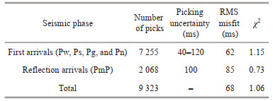
3.2.2 Traveltime tomography modeling of OBS dataPrior to traveltime picking and velocity inversion, clock correction, relocation, and band-pass filtering (5–15 Hz) were applied to each OBS with OBSTOOL software (Nakamura et al., 1987). Subsequently, all the first arrivals including Pw (direct water waves), Ps (refraction within the sediments), Pg (refraction within the crust), and Pn (refraction within the uppermost mantle) phases were manually picked with a time uncertainty of 40–120 ms depending on the offset and signal-to-noise ratio (Figs. 3–4 and Supplementary Figs. S1–S9). PmP (Moho reflections) phases were clearly identified on the seismic records of 7 OBSs (i.e., OBS 42 to OBS 48), and a picking uncertainty of 100 ms was assigned for PmP arrivals (Figs. 3–4 and Supplementary Figs.S3–S7).

|
| Fig.3 Observed and modeled data for OBS 48 a. seismic record of the vertical component; b. seismic record with observed and calculated travel times illustrated. Green bars indicate the first arrival (Pw, Ps, Pg, and Pn) traveltime picks and their associated uncertainties, while blue bars represent the PmP picks and their associated uncertainties. Red dots represent the calculated traveltimes through the final velocity model; c. calculated ray paths through the final velocity model. The thick black line indicates the PmP-inverted Moho reflector. The red triangles in (c) denote the locations of OBS stations. |

|
| Fig.4 Observed and modeled data for OBS 47 Display conventions are the same as in Fig. 3. |
The traveltime tomography modeling was performed using Tomo2D code (Korenaga et al., 2000), which is a grid-based inversion approach and allows the modeling of a velocity field by simultaneous inversion of both refraction and reflection arrivals. The iterative inversion requires an initial velocity model with a floating reflection interface and the picked refraction and reflection traveltimes. The initial velocity model of Line CFT2011 with the size of 200 km×35 km was defined by a sheared mesh hanging from the seafloor with a constant cell size of 250 m in both horizontal and vertical directions (Fig. 5a). The seafloor geometry was constrained by the MCS reflection profile of Line CFT2011 (Fig. 2a), and the velocity of water layer was set to 1.5 km/s. The velocity was assumed to gradually increase from 1.6 km/s at the seafloor to 8.0 km/s at the depth of 22 km, and then slowly increase to 8.5 km/s at the bottom of the model (Fig. 5a). To simultaneously model the PmP arrivals, a floating Moho reflector was set at the depth of 22 km with a node spacing of 250 m (Fig. 5a). During the iterative inversion, the horizontal correlation length was assumed to increase from 2.0 km near the seafloor to 5.0 km at the model bottom, and the vertical correlation length was set to increase from 0.5 km near the seafloor to 1.5 km at the model bottom. The depth kernel weighting factor of 0.2 was selected to favor velocity perturbations over interface depth perturbations, and the weighting factors of velocity and depth smoothing were set to 75 and 5, respectively. After 10 iterations, the final velocity model of Line CFT2011 (Fig. 5b) was obtained with an overall root-mean-square (RMS) misfit of 68 ms and a chi-square (χ2) value of 1.06. The misfit statistics for the iterative inversion are detailed in Table 1. The traveltime residuals exhibit significant reduction between the starting and final velocity models (Supplementary Fig.S10).

|
| Fig.5 Traveltime tomography inversion of the OBS data along Line CFT2011 a. initial velocity model; b. final velocity model; c. derivative weight sum. The red and black triangles denote the locations of OBS stations. The masked areas in (b) are not constrained by rays. The thick black line denotes Moho reflector. LNLU: Lingnan Low Uplift. |
|
Ray density through the final velocity model can be quantitatively represented by the derivative weight sum (Toomey and Foulger, 1989; Davy et al., 2016; Yu et al., 2018). In the central part (model distance of 20–130 km) of the final velocity model, the ray coverage is excellent (Fig. 5c), giving good constraints on the velocity there. In the model edges (model distance of 0–20 km and 130–200 km), the ray coverage is also good at depth shallower than 10 km, but poor at depth deeper than 10 km (Fig. 5c).
The velocity and Moho depth uncertainties of the final model arising from the initial model selection and the picking errors were quantitatively estimated by Monte Carlo uncertainty analysis (Korenaga et al., 2000) with a total of 100 inversion realizations (Fig. 6). We firstly generated 100 initial velocity models by randomizing the velocities of 4.0 km/s and 8.0 km/s by ±5% (3.8–4.2 km/s and 7.6–8.4 km/s, respectively). The depth of the initial Moho reflector was randomly perturbed by ±2.5 km. Subsequently, 100 noisy traveltime data sets were generated by adding random time errors including a common receiver error of ±60 ms and a picking error (±half the individual picking error, i.e., ±(20–60) ms). Finally, the tomography inversion was repeated with randomly selected pairs of initial velocity model, Moho reflector depth, and noisy traveltime data, using the same inversion parameters which generated the final velocity model (Fig. 5b). The RMS traveltime misfits of 100 inversions all reduce to ~75 ms (Fig. 6c–d), implying that all initial models have converged to final model. The Monte Carlo average velocity model (Fig. 6a) shows no obvious difference from the final velocity model (Fig. 5b). The Monte Carlo standard deviation, which is usually taken as a statistical assessment of the uncertainty in the average model (Davy et al., 2016; Yu et al., 2018), shows that the velocity uncertainties are mostly less than ±0.05 km/s (Fig. 6b). Moho depth uncertainty is less than ±0.2 km at model distance of 25–115 km, and ranges from ±0.2 km to ±0.5 km at model distance of 16–25 km and 115–130 km (Fig. 6b).

|
| Fig.6 Results of Monte Carlo uncertainty analysis a. average velocity model from 100 inversion realizations; b. standard deviation of the average velocity model. Root-mean-square (RMS) traveltime residuals for 100 models of the first (c) and last (d) iterations. The red triangles denote the locations of OBS stations. The thick black lines and black bars represent the average Moho depth and their standard deviations, respectively. |
The resolvable scale of the final velocity model was quantitatively estimated by checkerboard resolution tests. Three anomalies of different scales (35 km×7 km, 25 km×5 km, and 15 km×3 km, horizontally and vertically, respectively) with a sinusoidal velocity perturbation of ±5% were tested and analyzed (Fig. 7). The results exhibit that the large-scale anomalies of 35 km×7 km can be resolved excellently throughout the model except at depths larger than 21 km (Fig. 7). Middle-scale anomalies of 25 km×5 km are well recovered at depths shallower than 10 km throughout the model, and greatly recovered at depths between 10 km and 20 km in the middle section (25–125 km) of the model (Fig. 7). Poor recovery is obtained at depths of 10–20 km in the model edges (Fig. 7) owing to the limited ray coverage (Fig. 6c). Small-scale anomalies of 15 km×3 km appear to be greatly resolved at depths shallower than 9 km, but unresolvable below these depths (Fig. 7).

|
| Fig.7 Results of checkerboard resolution tests Initial (left) and recovered (right) velocity anomalies of three different scales of 35 km×7 km, 25 km×5 km, and 15 km×3 km (from top to bottom), horizontally and vertically, respectively. The black line denotes PmP-inverted Moho reflector. |
The results of the ray coverage, Monte Carlo uncertainty analysis, and checkerboard resolution tests give us confidence for the interpretation of deep crust-scale structures and shallow smaller structures in both the final velocity model (Fig. 5b) and the collocated MCS profile (Fig. 2).
4 RESULT 4.1 Seismic crustal structures of the southwestern QDNB of the SCSOn the MCS profile of Line CFT2011, the seafloor is fairly flat and imaged mostly at the depth of 0.4–1.6 s two-way traveltime (TWT; 0.3–1.2 km) in the southwestern QDNB (Figs. 2 & 8b). The basement reflections are relatively weak with moderate to poor continuity, and generally deepen northwestward from the depth of 2.2-s TWT at the southern edge of the QDNB to ~7-s TWT at the central Ledong Sag except at the Lingnan Low Uplift where a basement high is located (Fig. 8b). The Moho reflections are imaged with moderate to relatively poor continuity at the depth of ~9–10-s TWT (Figs. 2 & 8b). To make a joint and more robust interpretation, the velocity model of Line CFT2011 (Fig. 5b) is converted into TWT domain and then superimposed onto the collocated MCS section (Fig. 8c). The basement reflections correlate well with the velocity isocontour of 5 km/s, and the Moho reflections imaged on MCS profile show good correlation with the Moho reflector inverted from PmP phases recorded in OBS data (Fig. 8c). The velocities of the Moho are about 7 km/s in the Huaguang Sag and Lingnan Low Uplift, but close to 6.4 km/s in the central Ledong Sag (Fig. 8c). Constrained by the reflection and velocity structures along Line CFT2011, the crystalline crust is estimated to be 18 km thick at the southeastern Huaguang Sag, and generally thins northwestward except at the Lingnan Low Uplift where the crust is about 12–15 km thick (Fig. 5b). Beneath the central Ledong Sag, the thinnest (8 km) crust is found (Fig. 5b). The lower crust there has probably been extremely thinned and even absent, because the imaged Moho reflector gradually merges into the velocity isocontour of 6.4 km/s (Figs. 5b & 8c) which is usually treated as the boundary between the upper and lower crust (e.g., Ding et al., 2012; Pichot et al., 2014).

|
| Fig.8 Seismic section of Line CFT2011 across the southwestern QDNB a. free-air gravity anomaly (FAA) and magnetic anomaly (MA) along the section of Line CFT 2011; b. MCS section of Line CFT 2011; c. MCS section superimposed with the collocated velocity model of Line CFT2011. The black and blue circles indicate the basement and Moho imaged on MCS reflection profile, respectively. The blue line in (c) denotes PmP-inverted Moho reflector. LNLU: Lingnan Low Uplift. |
Along Line CFT2011, the sediments generally thicken from ~2.5 km at the southeastern Huaguang Sag to ~11 km at the central Ledong Sag except above the basement high of the Lingnan Low Uplift where the sediments are ~4.5 km thick (Fig. 5b). Within the deep sedimentary depression of the southwestern QDNB, a ~60-km-wide FRZ spanning from the central Ledong Sag to the northern Huaguang Sag is imaged with the thickness of ~3– 9 km (Figs. 2 & 8). The giant FRZ penetrates the Reflector T20 and extends upward to the Pleistocene sediments (Fig. 2b). The sedimentary sequences are generally clear and continuous by the side of this giant FRZ, e.g., at 75–90-km distance along MCS profile of Line CFT2011 (Figs. 2b & 8b). The velocity of this giant FRZ increases slowly with depth from ~2.5–3.0 km/s at the depth of ~2–3 km to ~5.0 km/s at the depth of ~8–11 km (Fig. 8c). The giant FRZ features distinct negative anomaly on the velocity anomaly profile along Line CFT2011 (Fig. 9a) which is calculated as the difference between the final velocity model (Fig. 5b) and its average 1-D velocity. On the vertical velocity gradient (VVG) profile of the final velocity model along Line CFT2011 (Fig. 9b), the giant FRZ correlates well with the low VVG zone where the VVG mostly ranges from 0.1/s to 0.3/s, while the sediments in the Huaguang Sag and Guangle Uplift slightly affected by fluid activities have the higher VVG of larger than 0.5/s.

|
| Fig.9 Velocity anomaly (a) and vertical velocity gradient (b) of the final velocity model along Line CFT2011 The velocity anomaly is calculated as the difference between the final velocity model and its average 1-D velocity. Thick black line denotes PmP-inverted Moho reflector. LNLU: Lingnan Low Uplift. |
For the large-scale FRZ within sedimentary depressions there are two candidate interpretations: (1) fluid charged sediments often rich in oil/gas and (2) magma intrusions (e.g., Karisiddaiah and Raju, 2002; Chen et al., 2013; Lei and Ren, 2016; Zhao et al., 2016; Wan et al., 2019). The former usually features lower seismic velocities than surrounding sequences, while the latter generally has higher velocities (e.g., Wu et al., 2009; Lei and Ren, 2016; Zhao et al., 2016; Man et al., 2018; Wang et al., 2020). In the deep sedimentary depression of the southwestern QDNB, the giant FRZ is about 60 km wide, 3–9 km thick, and located at the depth below the seafloor of ~1.8–10.5 km (Figs. 2 & 8–10). This giant FRZ features lower velocity than the surrounding sedimentary sequences at the same depth below the seafloor and the velocity difference is up to 1.5 km/s (Figs. 9a & 10a), thus the possibility that the giant FRZ was formed by magma intrusion can be ruled out, and fluid charging is probably a more plausible cause. Furthermore, the velocity of the giant FRZ increases slowly with depth with smaller VVG than that of the surrounding sediments (Figs. 9b & 10a). The smaller VVG of the giant FRZ indicates that enhanced low-velocity fluid infilling slowed down the velocity increasing with depth by reducing the velocity of the FRZ. The giant FRZ in the southwestern QDNB also has lower velocity and smaller VVG than the sediments at the same depth below the seafloor in the Zhongjiannan Basin (ZJNB; Pichot et al., 2014), ZRMB (Yan et al., 2001; Ding et al., 2012), and Southwest Taiwan Basin (SWTB; Wan et al., 2017) of the SCS (Fig. 10b) where the fluid activities are very weak or absent. In addition, the central section (profile distance of 20–50 km along CFT 2011) of the giant FRZ features weak magnetic anomaly (< ±20 nT) and low free-air gravity anomaly (from -25 to -50 mGal) (Fig. 8a), also supporting the interpretation of fluid charged sediments for this giant FRZ rather than magma intrusion.

|
| Fig.10 1-D velocity profiles extracted from the final velocity model of Line CFT2011 a. comparison of 1-D velocity profiles between the giant fuzzy reflection zone (FRZ) and its surrounding sediments; b. comparison of 1-D velocity profiles between the giant FRZ and the sediments in the Zhongjiannan Basin (ZJNB; Pichot et al., 2014), Zhujiang (Pearl) River Mouth Basin (ZRMB; Yan et al., 2001; Ding et al., 2012), and Southwest Taiwan Basin (SWTB; Wan et al., 2017) of the South China Sea (SCS). The grey shaded area represents the depth extent of the FRZ. The carmine and black lines denote the 1-D velocity profiles sampled every 5 km within the sediments of model distance of 20-50 km and 90-120 km, respectively. |
Within the overlying sediments of this giant FRZ, multiple bright spots, i.e., strong reflectors with high amplitudes are also observed at the depth of about 0.2–0.8 km below the seafloor (Figs. 2b, 8, & 11). Generally, the candidate causes for bright spots within sediments can be magma sills, coarse-grained sediments (e.g., sandstone, siltstone), and gas charging. Magma sills and coarse-grained sediments usually display positive polarity on MCS profiles, e.g., magma sills in the SWTB of the SCS (Liao et al., 2016; Li et al., 2021a), and coarse-grained sediments (sandstone/siltstone) in the central canyon of the QDNB (Sun et al., 2021). However, the bright spots in our case feature reverse polarity in the migrated profile (Fig. 11c) and common-midpoint (CMP) gather (Fig. 11d), more similar to that of gas-charged sediments previously recognized in the central QDNB (Wang et al., 2020; Sun et al., 2021). Furthermore, the reflection amplitudes of these bright spots increase with offset (Fig. 11d), consistent with the amplitude-versus-offset (AVO) features of gas-charged sediments (e.g., Wang et al., 2021b). Thus, these bright spots are probably gas-charged reservoirs within the shallow sediments. Between the shallow gas reservoirs and the deep FRZ, multiple normal faults and weak reflection zones that probably contain numerous minor fractures are imaged (Fig. 11a–b). The shallow gas reservoirs are then suggested to have a genetic link with the giant FRZ beneath them, and these normal faults and minor fractures provide effective pathways for gas migration from the deep FRZ to the shallow reservoirs (Fig. 11b). Therefore, we propose that the FRZ in the southwestern QDNB is a giant gas-charged zone within the sediments.

|
| Fig.11 Close-up view of the MCS section of Line CFT2011 Uninterpreted (a) and interpreted (b) MCS sections of Line CFT2011. See Fig. 8b for location. The box in (a) is enlarged in (c). Red lines in (b) denote the normal faults, while black dashed arrows indicate the directions of gas migration; d: common-midpoint (CMP) gather of the trace indicated by green line in (c). GR: gas reservoir. |
The formation of giant gas-charged zone in sedimentary basins requires abundant gas sources, driving forces and pathways for gas migration and infilling. Previous studies revealed that the Paleogene sediments rich in organic matters are very thick (up to 7.5 km) in the sedimentary depression of the southwestern QDNB, and the lower Oligocene (Yacheng formation) is the principal source rocks (Lei et al., 2011b; Wang et al., 2014, 2020; Zhang et al., 2016a; Man et al., 2018; Yang et al., 2018). The Yacheng formation in the deep depression of the southwestern QDNB consists of 2–4-km thick coal-measure mudstone, whose organic matters originate mainly from higher terrestrial plants and are favorable for hydrocarbon gas generation (Man et al., 2018; Wang et al., 2020). In addition, the sediments are about 5–11 km thick in the deep depression of the southwestern QDNB (Figs. 5b & 8), and the heat flow is 70–85 mW/m2 with a high average geothermal gradient of 3–4.6 ℃/100 m (Shi et al., 2017; Yang et al., 2018). The high heat flow, geothermal gradient, and large sediment thickness contributed to the maturation of the deep Paleogene organic matters and the gas generation in the deep depression (He et al., 2008; Huang et al., 2014; Yang et al., 2018; Liu et al., 2019; Wang et al., 2020). The thermal evolution degree of the source rocks is high, and the intensity of gas generation has reached to (50–100)×108 m3/km2 (Man et al., 2018). Thus, there are abundant hydrocarbon gas sources in the deep depression of the southwestern QDNB.
The overpressure system caused by undercompaction and gas generation probably provided the driving forces for the vertical gas migration. Thick Paleogene sediments rich in organic matters were deposited in the deep depression during the rifting with high sedimentation rates of 86– 300 m/Ma (Zhao et al., 2015b; Man et al., 2018; Yang et al., 2018; Wang et al., 2020). Meanwhile, the rapid subsidence with high subsidence rates of 20–100 m/Ma caused unbalanced compaction and overpressure within the thick Paleogene sediments (Zhao et al., 2013; Yang et al., 2018; Wang et al., 2020, 2021a). Since the early Pliocene, the subsidence and sedimentation rates have accelerated to 140 m/Ma and 150–630 m/Ma, respectively (Zhao et al., 2013, 2015b; Yang et al., 2018). Rapid subsidence and sedimentation loading have possibly contributed to the rising of overpressure within the deep Paleogene sediments of the southwestern QDNB. In addition, gas generation from the maturation of Paleogene organic matters could further increase the pressure (Su et al., 2012; Man et al., 2018; Yang et al., 2018). The typical pressure profile across the Ledong Sag showed that the Paleogene strata are in an overpressure sequence with high pressure coefficients of 2–2.4 (Yang et al., 2018). The overpressure system in the deep depression is sufficient to drive the gas migration.
The deep hydrocarbon gases also need pathways to migrate upward and infill into the shallower sediments. The newly discovered giant gas-charged zone is located above the NE-trended boundary faults, i.e., No. 13 Fault and Huaguangbei Fault (Figs. 2b & 8c), which were formed during rifting and rooted in the deeply buried Paleogene source rocks (Fig. 2b; Wang et al., 2020). In addition, numerous minor fractures/fissures are usually generated under overpressure, but generally unidentifiable on MCS profiles due to their very small displacements (XieHu, 2004; Xie, 2016; Li et al., 2021b). These faults and fractures probably provided effective pathways for the deep gases to migrate vertically (Fig. 12), and then controlled the formation and spatial distribution of the giant gas-charged zone.

|
| Fig.12 Schematic formation of the giant gas-charged zone in the southwestern QDNB The green arrows indicate the directions of gas migration from the Paleogene source rocks through minor fractures and pre-existing boundary faults. Red lines denote the normal faults, while black dashed arrows indicate gas infilling to form the gas reservoirs within the shallow sediments. |
The abundant hydrocarbon gas sources, overpressure system, and effective migration pathways in the deep depression imply that the giant gas-charged zone in the southwestern QDNB probably contains rich hydrocarbon gases, although we cannot exclude the possibility that some non-hydrocarbon gases (carbon dioxide, nitrogen, etc.) from the deep crust contribute to its formation. Therefore, we propose that under overpressure the hydrocarbon gases generated within the deep Paleogene sediments have transported upward through the pre-existing boundary faults and the minor fractures, and then formed the giant gas-charged zone in the deep depression of the southwestern QDNB (Fig. 12). The gases subsequently migrated upward from the deep giant gas-charged zone, and formed the shallow gas reservoirs within the overlying sediments (Fig. 12).
5.3 Distribution of the giant gas-charged zone and implications for future natural gas explorationMCS profiles of the adjacent Lines MCS-L1 (Fig. 13a) and MCS-L2 (Fig. 13b) are presented and interpreted to help us reveal the distribution of the giant gas-charged zone and evaluate the potential of natural gas resources in the southwestern QDNB. The reflection profile of Line MCS-L1 in NNW-SSE direction (Fig. 13c) shows that the giant gas-charged zone is about 40 km wide and extends form the Paleogene strata upward to the lower Pleistocene sediments with the thickness > 3.5-s TWT (Fig. 13a). The profile MCS-L2 in SWW-NEE direction (Fig. 13c) reveals a larger width of ~68 km for the giant gas-charged zone (Fig. 13b). Above this giant gas-charged zone, some bright spots with high reflection amplitudes are also observed within the Pleistocene sediments and the reflections below are weak, representing shallow gas reservoirs formed by gas infilling from the giant gas-charged zone through the faults and minor fractures (Fig. 13a–b). Constrained by the three MCS profiles of Lines CFT2011, MCS-L1, and MCS-L2, the plane distribution of the giant gas-charged zone in the southwestern QDNB is approximatively shaped as a trapezoid of ~1 900 km2 (Fig. 13c). Then the volume of this giant gas-charged zone is roughly estimated to be ~11 400 km3 assuming an average thickness of 6 km.

|
| Fig.13 MCS reflection profiles MCS-L1 and MCS-L2 and distribution of the giant gas-charged zone a. MCS reflection profile of Line MCS-L1; b. MCS reflection profile of Line MCS-L2; c. plane distribution of the giant gas-charged zone in the bathymetric map. The carmine lines in (c) indicate the extent of the giant gas-charged zone imaged on MCS profiles, and the grey shaded area denotes the plane distribution of this giant gas-charged zone. GR: gas reservoir; HGB Fault: Huaguangbei Fault; LNLU: Lingnan Low Uplift. |
The discovery of the giant gas-charged zone and associated numerous shallow gas reservoirs implies that the deep sedimentary depression of the southwestern QDNB is rich in natural gases, and provides potential targets for future gas exploration.
6 CONCLUSIONTo reveal the origin and distribution of the giant FRZ imaged within the deep sedimentary depression of the southwestern QDNB, the OBS data along Line CFT2011 are processed with focus on the velocity structures and analyzed together with the coincident and adjacent MCS profiles. The primary findings and conclusions are as follows:
(1) The giant FRZ features lower velocity with difference up to 1.5 km/s and smaller vertical velocity gradient than the surrounding sedimentary sequences at the same depth, indicating enhanced fluid infilling that leads to velocity decrease. Above this giant FRZ, bright spots with reverse polarity are imaged at the depth of about 0.2–0.8 km below the seafloor and their reflection amplitudes increase with offset, agreeing with the reflection polarity and AVO features of gas-charged sediments. Therefore, these bright spots are probably shallow gas reservoirs with gases sourced from the deep FRZ, and then the FRZ is proposed to be a giant gas-charged zone within the sediments.
(2) This gas-charged zone extends from the Paleogene strata upward to the lower Pleistocene sediments, and is about 3–9 km thick. It appears as about 60 km, 40 km, and 68 km wide on adjacent MCS profiles CFT2011, MCS-L1, and MCS-L2. Constrained by these MCS profiles, the giant gas-charged zone in the southwestern QDNB is roughly estimated to cover an approximative trapezoid-shaped area of ~1 900 km2, and host a volume of ~11 400 km3 assuming an average thickness of 6 km.
(3) This giant gas-charged zone probably contains abundant hydrocarbon gases, which are generated from the deep Paleogene source rocks and transported upward via the pre-existing boundary faults and the minor fractures formed under overpressure. The newly discovered giant gas-charged zone and associated numerous shallow gas reservoirs imply huge natural gas potential in the deep sedimentary depression of the southwestern QDNB, and provide potential targets for future gas exploration.
7 DATA AVAILABILITY STATEMENTThe seismic data that support the findings of this study are available from the corresponding author upon reasonable request.
8 ACKNOWLEDGMENTWe thank the crew and scientists of R/Vs Tanbao and Dongfangkantan No. 1 for seismic data collection. Dr. Pengchun LI from South China Sea Institute of Oceanology, Chinese Academy of Sciences, is acknowledged for insightful discussions. We also thank two anonymous reviewers for their crucial and constructive comments. Some of the figures in this study are generated with Generic Mapping Tools (GMT) (Wessel and Smith, 1995).
Electronic supplementary materialSupplementary material (Supplementary Figs.S1– S10) is available in the online version of this article at https://doi.org/10.1007/s00343-022-1452-3.
Baraza J, Ercilla G. 1996. Gas-charged sediments and large pockmark-like features on the Gulf of Cadiz slope (SW Spain). Marine and Petroleum Geology, 13(2): 253-261.
DOI:10.1016/0264-8172(95)00058-5 |
Cai Z R, Xia B, Lü B F, et al. 2015. Initial rifting process and dynamics mechanism of Huaguang Sag: evidence from a numerical modeling method. Journal of Earth Science, 26(3): 399-406.
DOI:10.1007/s12583-014-0502-y |
Chen D X, Wu S G, Dong D D, et al. 2013. Focused fluid flow in the Baiyun Sag, northern South China Sea: implications for the source of gas in hydrate reservoirs. Chinese Journal of Oceanology and Limnology, 31(1): 178-189.
DOI:10.1007/s00343-013-2075-5 |
Chen X, Dong Y W, Hao G L. 2010. Magmatic activities and their influences on hydrocarbon accumulation in the early Permian, Central Tarim Basin. Geological Science and Technology Information, 29(5): 78-83.
(in Chinese with English abstract) |
Clift P D, Sun Z. 2006. The sedimentary and tectonic evolution of the Yinggehai-Song Hong basin and the southern Hainan margin, South China Sea: implications for Tibetan uplift and monsoon intensification. Journal of Geophysical Research, 111(B6): B06405.
DOI:10.1029/2005JB004048 |
Davy R G, Minshull T A, Bayrakci G, et al. 2016. Continental hyperextension, mantle exhumation, and thin oceanic crust at the continent-ocean transition, West Iberia: new insights from wide-angle seismic. Journal of Geophysical Research: Solid Earth, 121(5): 3177-3199.
DOI:10.1002/2016JB012825 |
Ding W W, Schnabel M, Franke D, et al. 2012. Crustal structure across the northwestern margin of South China Sea: evidence for magma-poor rifting from a wide-angle seismic profile. Acta Geologica Sinica (English Edition), 86(4): 854-866.
DOI:10.1111/j.1755-6724.2012.00711.x |
He J X, Chen S H, Liu H L, et al. 2008. Petroleum resource potential and advantageous exploration targets in Ying-Qiong Basin, northern margin of South China Sea. Natural Gas Geoscience, 19(4): 492-498.
(in Chinese with English abstract) |
Hu H Y. 2004. Overpressure cause and it affects the reserve formation. Natural Gas Geoscience, 15(1): 99-102.
(in Chinese with English abstract) |
Huang B J, Wang Z F, Liang G. 2014. Natural gas source and migration-accumulation pattern in the central canyon, the deep water area, Qiongdongnan basin. China Offshore Oil and Gas, 26(5): 8-14.
(in Chinese with English abstract) |
Huang B J, Xiao X M, Dong W L. 2002. Multiphase natural gas migration and accumulation and its relationship to diapir structures in the DF1-1 gas field, South China Sea. Marine and Petroleum Geology, 19(7): 861-872.
DOI:10.1016/S0264-8172(02)00109-5 |
Karisiddaiah S M, Subba Raju L V. 2002. Scenario of gas-charged sediments and gas hydrates in the western continental margin of India. Journal of Geophysics, 23(2): 33-41.
|
Korenaga J, Holbrook W S, Kent G M, et al. 2000. Crustal structure of the Southeast Greenland margin from joint refraction and reflection seismic tomography. Journal of Geophysical Research, 105(B9): 21591-21614.
DOI:10.1029/2000jb900188 |
Lei C, Ren J Y. 2016. Hyper-extended rift systems in the Xisha Trough, northwestern South China Sea: implications for extreme crustal thinning ahead of a propagating ocean. Marine and Petroleum Geology, 77: 846-864.
DOI:10.1016/j.marpetgeo.2016.07.022 |
Lei C, Ren J Y, Clift P D, et al. 2011a. The structure and formation of diapirs in the Yinggehai-Song Hong Basin, South China Sea. Marine and Petroleum Geology, 28(5): 980-991.
DOI:10.1016/j.marpetgeo.2011.01.001 |
Lei C, Ren J Y, Li X S, et al. 2011b. Structural characteristics and petroleum exploration potential in the deep-water area of the Qiongdongnan Basin, South China Sea. Petroleum Exploration and Development, 38(5): 560-569.
(in Chinese with English abstract) |
Lei C, Ren J Y, Pei J X, et al. 2021. Tectonics of the offshore Red River Fault recorded in the junction of the Yinggehai and Qiongdongnan Basins. Science China Earth Sciences, 64(11): 1893-1908.
DOI:10.1007/s11430-020-9796-2 |
Li B A, Tang Q S, Yan P, et al. 2021a. Characteristics of a laccolith along the LRTPB fault zone between Pearl River Mouth Basin and Southwest Taiwan Basin. Terrestrial, Atmospheric and Oceanic Sciences, 32(4): 443-458.
DOI:10.3319/TAO.2021.09.07.01 |
Li C, Luo X R, Fan C W, et al. 2021b. Generation mechanism of overpressure and its implication for natural gas accumulation in Miocene reservoir in Ledong A structrure, Ledong slope, Yinggehai Basin. Chinese Journal of Geology, 56(4): 1034-1051.
(in Chinese with English abstract) DOI:10.12017/dzkx.2021.054 |
Liao W Z, Lin A T, Liu C S, et al. 2016. A study on tectonic and sedimentary development in the rifted northern continental margin of the South China Sea near Taiwan. Interpretation, 4(3): SP47-SP65.
DOI:10.1190/INT-2015-0209.1 |
Liu J, Yang R, Zhang J H, et al. 2019. Gas hydrate accumulation conditions in the Huaguang Depression of Qiongdongnan Basin and prediction of favorable zones. Marine Geology & Quaternary Geology, 39(1): 134-142.
(in Chinese with English abstract) DOI:10.16562/j.cnki.0256-1492.2018072701 |
Liu J B, Sun Z, Wang Z F, et al. 2015. Tectonic differences between eastern and western sub-basins of the Qiongdongnan Basin and their dynamics. Marine Geophysical Research, 36(1): 61-79.
DOI:10.1007/s11001-014-9247-3 |
Man X, Zhu J T, Yao Z, et al. 2018. The characteristic of Mud-Fluid diapir and its control on hydrocarbon accumulation in deep water area, Qiongdongnan Basin. Contributions to Geology and Mineral Resources Research, 33(2): 257-263.
(in Chinese with English abstract) DOI:10.6053/j.issn.1001-1412.2018.02.012 |
Nakamura Y, Donoho P L, Roper P H, et al. 1987. Large-offset seismic surveying using ocean-bottom seismographs and air guns: instrumentation and field technique. Geophysics, 52(12): 1601-1611.
DOI:10.1190/1.1442277 |
Pichot T, Delescluse M, Chamot-Rooke N, et al. 2014. Deep crustal structure of the conjugate margins of the SW South China Sea from wide-angle refraction seismic data. Marine and Petroleum Geology, 58: 627-643.
DOI:10.1016/j.marpetgeo.2013.10.008 |
Shi X B, Yu C H, Chen M, et al. 2017. Analyses of variation features and influential factors of heat flow in the northern margin of the South China Sea. Earth Science Frontiers, 24(3): 56-64.
(in Chinese with English abstract) DOI:10.13745/j.esf.2017.03.005 |
Su L, Zheng J J, Wang Q, et al. 2012. Formation mechanism and research progress on overpressure in the Qiongdongnan Basin. Natural Gas Geoscience, 23(4): 662-672.
(in Chinese with English abstract) |
Sun Q L, Xie X N, Wu S G, et al. 2021. Thrust faults promoted hydrocarbon leakage at the compressional zone of fine-grained mass-transport deposits. Frontiers in Earth Science, 9: 764319.
DOI:10.3389/feart.2021.764319 |
Sun Z, Wang Z F, Sun Z P, et al. 2015. Structure and kinematic analysis of the deepwater area of the Qiongdongnan Basin through a seismic interpretation and analogue modeling experiments. Acta Oceanologica Sinica, 34(4): 32-40.
DOI:10.1007/s13131-015-0585-z |
Toomey D R, Foulger G R. 1989. Tomographic inversion of local earthquake data from the Hengill-Grensdalur Central Volcano Complex, Iceland. Journal of Geophysical Research, 94(B12): 17497-17510.
DOI:10.1029/JB094iB12p17497 |
Wan K Y, Xia S H, Cao J H, et al. 2017. Deep seismic structure of the northeastern South China Sea: origin of a high-velocity layer in the lower crust. Journal of Geophysical Research: Solid Earth, 122(4): 2831-2858.
DOI:10.1002/2016JB013481 |
Wan Z F, Yao Y J, Chen K W, et al. 2019. Characterization of mud volcanoes in the northern Zhongjiannan Basin, western South China Sea. Geological Journal, 54(1): 177-189.
DOI:10.1002/gj.3168 |
Wang L J, Zhu J T, Zhuo H T, et al. 2020. Seismic characteristics and mechanism of fluid flow structures in the central depression of Qiongdongnan basin, northern margin of South China Sea. International Geology Review, 62(7-8): 1108-1130.
DOI:10.1080/00206814.2019.1695002 |
Wang W L, Dong D D, Wang X J, et al. 2021a. Three-stage tectonic subsidence and its implications for the evolution of conjugate margins of the southwest subbasin, South China Sea. Journal of Oceanology and Limnology, 39(5): 1854-1870.
DOI:10.1007/s00343-020-0259-3 |
Wang X, Yan P, Yu J H, et al. 2021b. Seismic detection for hydrocarbon in mud volcano-rich area southwest to the Dongsha Island. Earth Science, 46(2): 621-631.
(in Chinese with English abstract) DOI:10.3799/dqkx.2020.069 |
Wang Z F, Huang B J. 2008. Dongfang 1-1 gas field in the mud diapir belt of the Yinggehai Basin, South China Sea. Marine and Petroleum Geology, 25(4-5): 445-455.
DOI:10.1016/j.marpetgeo.2008.01.004 |
Wang Z S, Liu Z, Sun Z P, et al. 2014. Preliminary prediction and evaluation of Oligocene source rocks in Ledong-Lingshui Sag in deep-water area of Qiongdongnan Basin. Journal of Central South University (Science and Technology), 45(3): 876-888.
(in Chinese with English abstract) |
Wessel P, Smith W H F. 1995. New version of the generic mapping tools. Eos, Transactions American Geophysical Union, 76(33): 329.
DOI:10.1029/95eo00198 |
Wu S M, Qiu X L, Zhou D, et al. 2009. Crustal structure beneath Yinggehai basin and adjacent Hainan Island, and its tectonic implications. Journal of Earth Science, 20(1): 13-26.
DOI:10.1007/s12583-009-0002-7 |
Wu T T, Wei J G, Liu S X, et al. 2020. Characteristics and formation mechanism of seafloor domes on the north-eastern continental slope of the South China Sea. Geological Journal, 55(1): 1-10.
DOI:10.1002/gj.3402 |
Xie Y H. 2016. Hydrocarbon accumulation mechanism and resource prospect of HTHP natural gas reservoirs in Western South China Sea: a case study on the Ying-Qiong Basin. Oil Drilling & Production Technology, 38(6): 713-722.
(in Chinese with English abstract) DOI:10.13639/j.odpt.2016.06.001 |
Xie Y H, Wang Z F, Tong C X. 2008. Petroleum geology of Yacheng 13-1, the largest gas field in China's offshore region. Marine and Petroleum Geology, 25(4-5): 433-444.
DOI:10.1016/j.marpetgeo.2008.01.006 |
Yan P, Zhou D, Liu Z S. 2001. A crustal structure profile across the northern continental margin of the South China Sea. Tectonophysics, 338(1): 1-21.
DOI:10.1016/s0040-1951(01)00062-2 |
Yang D S, Zhao Z G, Yang H Z, et al. 2018. Diapir structure and its significance to hydrocarbon accumulation in Ledong-Lingshui sag, the Qiongdongnan Basin. China Petroleum Exploration, 23(3): 64-73.
(in Chinese with English abstract) DOI:10.3969/j.issn.1672-7703.2018.03.008 |
Yang R, Yan P, Wu N Y, et al. 2014. Seismic reflecting characteristics of fluid and its effect on gas hydrate distribution in the Shenhu Area, South China Sea. Journal of Marine Sciences, 32(4): 19-26.
(in Chinese with English abstract) DOI:10.3969/j.issn.1001-909X.2014.04.003 |
Yu J H, Yan P, Wang Y L, et al. 2018. Seismic evidence for tectonically dominated seafloor spreading in the Southwest Sub-basin of the South China Sea. Geochemistry, Geophysics, Geosystems, 19(9): 3459-3477.
DOI:10.1029/2018GC007819 |
Zhang G C, Zeng Q B, Su L, et al. 2016a. Accumulation mechanism of LS 17-2 deep water giant gas field in Qiongdongnan Basin. Acta Petrolei Sinica, 37(S1): 34-46.
(in Chinese with English abstract) DOI:10.7623/syxb2016S1004 |
Zhang G X, Chen F, Yang S X, et al. 2012. Accumulation and exploration of gas hydrate in deep-sea sediments of northern South China Sea. Chinese Journal of Oceanology and Limnology, 30(5): 876-888.
DOI:10.1007/s00343-012-1313-6 |
Zhang Q, Jin W J, Wang J R, et al. 2016b. Relationship between magma-thermal field and hydrocarbon accumulation. Progress in Geophysics, 31(4): 1525-1541.
(in Chinese with English abstract) DOI:10.6038/pg20160416 |
Zhang W, Liang J Q, He J X, et al. 2017. Characteristics of mud diapir and gas chimney and their relationship with reservoir forming for petroleum and natural gas hydrate on northern slope of the South China Sea. Marine Geology Frontiers, 33(7): 11-23.
(in Chinese with English abstract) DOI:10.16028/j.1009-2722.2017.07002 |
Zhao Y H, Tong D J, Song Y, et al. 2016. Seismic reflection characteristics and evolution of intrusions in the Qiongdongnan Basin: implications for the rifting of the South China Sea. Journal of Earth Science, 27(4): 642-653.
DOI:10.1007/s12583-016-0708-2 |
Zhao Z X, Sun Z, Wang Z F, et al. 2013. The dynamic mechanism of post-rift accelerated subsidence in Qiongdongnan Basin, northern South China Sea. Marine Geophysical Research, 34(3): 295-308.
DOI:10.1007/s11001-013-9188-2 |
Zhao Z X, Sun Z, Wang Z F, et al. 2015a. The mechanics of continental extension in Qiongdongnan Basin, northern South China Sea. Marine Geophysical Research, 36(2): 197-210.
DOI:10.1007/s11001-014-9238-4 |
Zhao Z X, Sun Z, Wang Z F, et al. 2015b. The high resolution sedimentary filling in Qiongdongnan Basin, Northern South China Sea. Marine Geology, 361: 11-24.
DOI:10.1016/j.margeo.2015.01.002 |
Zhu W L, Huang B J, Mi L J, et al. 2009. Geochemistry, origin, and deep-water exploration potential of natural gases in the Pearl River Mouth and Qiongdongnan basins, South China Sea. AAPG Bulletin, 93(6): 741-761.
DOI:10.1306/02170908099 |
Zhu W L, Zhang G C, Zhong K. 2016. Oil and gas exploration progress of China National Offshore Oil Corporation during the 12th Five-Year Plan and the prospect during the 13th Five-Year Plan. China Petroleum Exploration, 21(4): 1-12.
(in Chinese with English abstract) DOI:10.3969/j.issn.1672-7703.2016.04.001 |